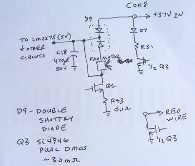
Maytronics Rev 03 board partial schematic
by thehobe
(Northern California)

Rev 03 partial schematic
This is for you, Gibson. A partial schematic of the board to show you how the input circuit is connected in the motor control unit. One side of the D9, TO220 case dual shottky rectifier isolates the power cable capacitance from the control board while the other side is used as a "catch" diode for the reverse EMF generated by the pump motor, limiting the "kickback" voltage excursion on the drain of DMOS, Q6. C18, the 470uF capacitor is used to decouple the remainder of the motor control circuit electronics. D7 is used in series with R31 to feed 1.5 Amps for a short period of time to the land based power unit either for shutoff or calibration of the shutoff value. The track motor is fed off of C18, through the reversing relay to the motor, returning through Q1 and R14, the 0.15 Ohm 3W sense R for the track motor current. The propeller motor is fed through D9 to the motor, returning through Q6 and R43, the 0.1 Ohm, 2W sense R for the track motor current.
I will attempt to add a photo of the partial circuit.


